MENU

/
/
Adjustment of high-frequency welded pipe machine

Adjustment of high-frequency welded pipe machine

  • Sort:Information
  • Auth:
  • Source:
  • Release time:2022-12-07 11:30
  • Pvs:

【概要描述】The high-frequency welded pipe machine is the leading equipment of the welded pipe production line. The normal operation of the unit plays a vital role in improving production efficiency, increasing economic benefits, and ensuring product quality. Therefore, the adjustment of high-frequency welded pipe machine, as well as the accurate judgment and timely treatment of faults, are particularly important. Below we focus on the following aspects to be discussed.

Adjustment of high-frequency welded pipe machine

【概要描述】The high-frequency welded pipe machine is the leading equipment of the welded pipe production line. The normal operation of the unit plays a vital role in improving production efficiency, increasing economic benefits, and ensuring product quality. Therefore, the adjustment of high-frequency welded pipe machine, as well as the accurate judgment and timely treatment of faults, are particularly important. Below we focus on the following aspects to be discussed.

  • Sort:Information
  • Auth:
  • Source:
  • Release time:2022-12-07 11:30
  • Pvs:
Detail

The high-frequency welded pipe machine is the leading equipment of the welded pipe production line. The normal operation of the unit plays a vital role in improving production efficiency, increasing economic benefits, and ensuring product quality. Therefore, the adjustment of high-frequency welded pipe machine, as well as the accurate judgment and timely treatment of faults, are particularly important. Below we focus on the following aspects to be discussed.


Adjust

The adjustment we are talking about here refers to the debugging work when the hole type is installed. As long as the tube blank can run normally and smoothly in the unit and produce qualified products, it can be said that the adjustment task has been completed. In subsequent production, a series of adjustments made should be incorporated into troubleshooting. As far as the adjustment of the high-frequency welded pipe machine is concerned, it should be divided into the following steps.


①Preparations

The preparation work mainly refers to the inspection of the quality of the rolls and the inspection of the condition of the equipment. Roll quality inspection should focus on the shape of the pass. During inspection, you can use the pass template to check whether the pass of each roll meets the design requirements, otherwise it will be removed and cannot be installed and used. In addition, special attention should be paid to the size requirements of the bottom diameter of the rolls, because this is the key data to ensure that the rolls are matched when the rolls are running synchronously. Paired rolls must be of equal size and shape. When checking the condition of the equipment, it can be summed up in the following sentences.


That is, the flat shaft should be flat, the vertical shaft should be straight, the positioning of the rolls should not move, the sliding parts should be flexible and not swing, and the adjustment should be free. The fixed part must be firm, the movable part must be flexible, and there should be no phenomenon of "moving, shaking, and back and forth". If the above requirements are not met, the equipment must be overhauled to restore its most basic performance requirements.


②Align

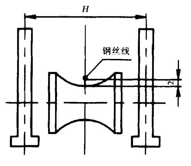
The hole pattern alignment is the first step in the adjustment work. When alignment, a steel wire of φ0.5mm can be used. The basic length is from the feeding roller of the forming machine to the straightening roller of the sizing machine to determine the rolling line. in the after the center position, tighten the steel wire to fix it. The height of the steel wire should be slightly higher than the bottom diameter of the flat roller by more than 2 mm (Figure 1). This steel wire is the center reference line when the hole pattern is aligned.
 

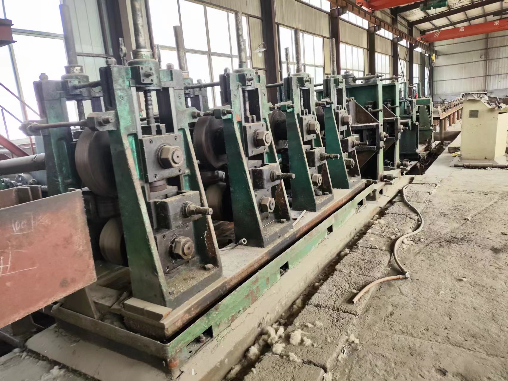
High-frequency welded pipe machine


③Flat roll alignment

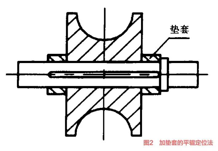
There are two alignment methods for flat rolls: one is to configure different thickness of fixed gaskets according to the thickness of each pass roll (Figure 2).


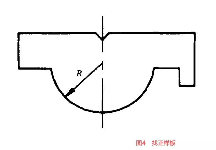
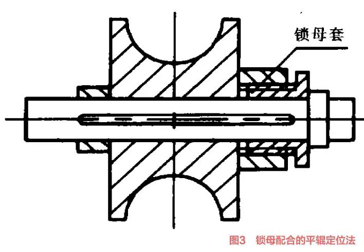
If the requirements are not met, accumulated errors are likely to occur after assembly, which directly affects the effect of hole alignment. The second is to adjust the position of the roll on the shaft with the lock nut (Figure 3), so that the center of the pass of each roll can coincide with the center line. The positioning of the center of the hole pattern is checked with a special template (Fig. 4). When checking, put the template into the aligned hole pattern, and then slowly lift the upper end. When the steel wire can smoothly fall into the center groove of the template, it means that the center position of the hole pattern is correct, otherwise it needs to do axial Mobile adjustment. This is a relatively simple way to get it right.
 

High-frequency welded pipe machine


High-frequency welded pipe machine


High-frequency welded pipe machine


The alignment of the upper flat roll is based on the lower flat roll. After calculating the shaft distance of the upper and lower flat rollers, adjust the upper flat roller to the horizontal position. The calculation method of the shaft spacing is as follows. Calculation of shaft spacing of open hole type:


High-frequency welded pipe machine


Calculation of shaft spacing for closed hole pattern:


High-frequency welded pipe machine


formula:

Under D: is the bottom diameter of the lower roller, mm;

Upper D: is the outer diameter of the upper roller, mm;

t: is the thickness of the tube blank, mm;

R : is the diameter of the sizing hole, mm;

a: is the reduction coefficient (0.1~0.5).


The reduction amount of the coefficient a in the formula is mainly selected according to the thickness of the tube blank, the reduction of the outer diameter of the tube and the size of the specification, as well as the actual situation such as the shaft diameter and the elastic deformation of the shaft. However, the cold rolling phenomenon cannot occur on the forming machine. Whether the selection of the pressing amount is reasonable can be measured and checked by the pressing marks of the brazing wire. When sampling, first start the unit, drive to the slowest speed, and then bend the brazing wire with a diameter slightly larger than the thickness of the tube blank into a shape roughly similar to the hole shape, and slowly feed it into the rolling mill to obtain the indentation of the brazing wire.


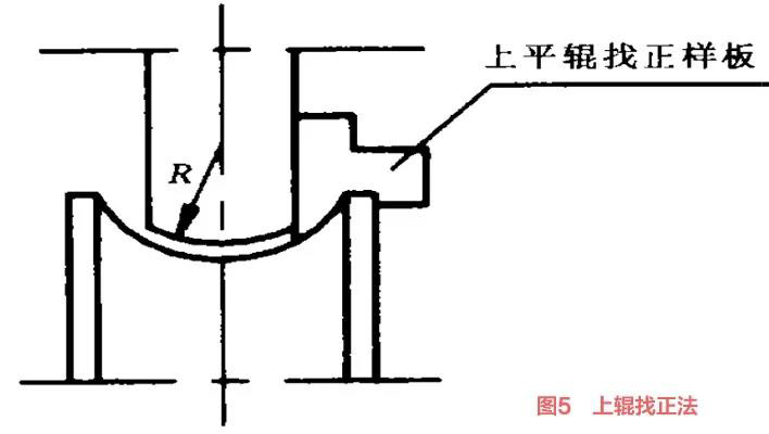
After the upper roller is leveled, the axial center position of the upper roller of the open hole pattern can also be centered with a sample plug gauge to check whether the two side clearances of the lower roller hole pattern and the upper roller hole pattern are the same (Figure 5). If the same, the axial position of the upper roller can be locked. The closed hole pattern can be touched by touch to check whether the upper and lower hole patterns are consistent.
 

High-frequency welded pipe machine


④Vertical roller alignment

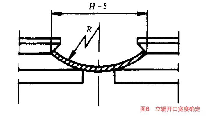
Vertical roll alignment can be divided into three steps: the first step is to determine the opening gap of each set of vertical rolls, that is, the axial distance between the two vertical rolls; then find the center position of each set of vertical rolls; finally, adjust the vertical rolls high. The opening gap of the vertical roller is based on the deformation opening width in the design of the pass pattern, and then it is appropriate to shrink it by about 5 mm (Fig. 6).
 

High-frequency welded pipe machine


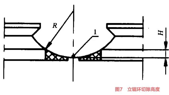
When the shrinkage is too large, the wear of the upper edge of the vertical roller hole pattern will be accelerated, and the load of the equipment will also be increased. The center of the vertical roller should be aligned with the flat roller at the same time to ensure that the center position of the vertical roller of the flat roller is on the same center line. After finding the center line of the vertical roll pass, you can drop the steel wire on the bottom diameter of the flat roll pass, and start to find the height of the vertical roll. The height of the vertical roller is based on the height of the lower edge of the vertical roller pass and the height of the steel wire (Figure 7),
 

High-frequency welded pipe machine


The height of the vertical rollers before forming depends on the process parameters of the cut-off amount of the roller ring under the vertical roller (the part of the mesh line in the figure is the cut-off part of the roller ring).


⑤Alignment of other hole types

For other hole alignment methods, refer to the alignment principle of flat rollers and vertical rollers, except that the bottom diameter of the guide roller should be slightly higher than the reference line by 0.5-2 mm (depending on the size of the pipe diameter and depending on the wall thickness). The burr idler should be 0.5mm higher than the reference line, so that the force is more stable when the outer burr is planed, and the planing jump is prevented.


Generally, the adjustment of high-frequency welded pipe machine includes preparation work, alignment, alignment of flat rollers, alignment of vertical rollers, and alignment of other pass types, so that the normal operation of the unit can improve production efficiency, increase economic benefits, and ensure product quality. etc. have played an important role.

关键词:

More News

Analyzing of Double head uncoiler
Time of issue : 2024-11-06
Analysis of a double-head uncoiler:

Analysis of Double-Head Uncoiler Introduction:
A double-head uncoiler is a crucial piece of equipment in metal processing industries. It is primarily used to feed metal coils into roll forming machines, cut-to-length lines, or slitting lines. The double-head design allows for continuous operation by enabling one coil to be loaded and prepared while the other coil is being processed.

Key Components:
1.Mandrels:The double-head uncoiler features two mandrels, each designed to hold and unwind a coil of metal. These mandrels are typically hydraulic or motor-driven to control the unwinding process.
2.Coil Carriages:These assist in loading and unloading coils onto the mandrels. Coil carriages help to position the coils correctly and securely.
3.Hydraulic System:This system is used to expand the mandrel to grip the inner diameter of the coil securely.
4.Control System:The electronic control system automates the switching between coils and ensures synchronization with the subsequent processing line.
5.Brake System:To control the speed of uncoiling and ensure smooth feeding into the processing line, a braking system (mechanical or pneumatic) is integrated.

Operation:
1.Loading:One coil is loaded onto a mandrel with the assistance of a coil carriage. The hydraulic system secures the coil.
2.Preparation:While one coil is being processed, the second coil can be prepared on the other mandrel.
3.Uncoiling:The control system manages the unwinding process, adjusting speed and tension to match the requirements of downstream equipment.
4.Switching Coils:Once the first coil is nearly depleted, the system can seamlessly switch to the second coil, ensuring continuous operation without stopping the line.
Advantages:
1.Continuous Operation:Allows for non-stop processing as one coil can be prepared while the other is being used.
2.Increased Efficiency:Reduces downtime and increases overall productivity in the metal processing line.
3.Improved Safety:Automated systems reduce the need for manual handling of heavy metal coils.
4.Precise Control:Advanced control systems provide precise management of coil unwinding, contributing to product quality and consistency.

Applications:
Double-head uncoilers are widely used in industries such as:
- Steel production and processing- Automotive manufacturing- Construction material production- Electrical appliance manufacturing Conclusion:
Double-head uncoilers are essential in facilitating efficient and continuous production processes in various metalworking industries. Their automation and robust design contribute significantly to operational efficiency, safety, and overall productivity.

For more information, please pay attention to the website of Jinyujie Mechanical and Electrical Used Pipe Mill Supplier:www.usedpipemill.com

JinYuJie-Used Pipe Mills Supplier(Please click the link→) :second-hand pipe mill
Detail
Analysis of a double-head uncoiler:

Analysis of Double-Head Uncoiler Introduction:
A double-head uncoiler is a crucial piece of equipment in metal processing industries. It is primarily used to feed metal coils into roll forming machines, cut-to-length lines, or slitting lines. The double-head design allows for continuous operation by enabling one coil to be loaded and prepared while the other coil is being processed.

Key Components:
1.Mandrels:The double-head uncoiler features two mandrels, each designed to hold and unwind a coil of metal. These mandrels are typically hydraulic or motor-driven to control the unwinding process.
2.Coil Carriages:These assist in loading and unloading coils onto the mandrels. Coil carriages help to position the coils correctly and securely.
3.Hydraulic System:This system is used to expand the mandrel to grip the inner diameter of the coil securely.
4.Control System:The electronic control system automates the switching between coils and ensures synchronization with the subsequent processing line.
5.Brake System:To control the speed of uncoiling and ensure smooth feeding into the processing line, a braking system (mechanical or pneumatic) is integrated.

Operation:
1.Loading:One coil is loaded onto a mandrel with the assistance of a coil carriage. The hydraulic system secures the coil.
2.Preparation:While one coil is being processed, the second coil can be prepared on the other mandrel.
3.Uncoiling:The control system manages the unwinding process, adjusting speed and tension to match the requirements of downstream equipment.
4.Switching Coils:Once the first coil is nearly depleted, the system can seamlessly switch to the second coil, ensuring continuous operation without stopping the line.
Advantages:
1.Continuous Operation:Allows for non-stop processing as one coil can be prepared while the other is being used.
2.Increased Efficiency:Reduces downtime and increases overall productivity in the metal processing line.
3.Improved Safety:Automated systems reduce the need for manual handling of heavy metal coils.
4.Precise Control:Advanced control systems provide precise management of coil unwinding, contributing to product quality and consistency.

Applications:
Double-head uncoilers are widely used in industries such as:
- Steel production and processing- Automotive manufacturing- Construction material production- Electrical appliance manufacturing Conclusion:
Double-head uncoilers are essential in facilitating efficient and continuous production processes in various metalworking industries. Their automation and robust design contribute significantly to operational efficiency, safety, and overall productivity.

For more information, please pay attention to the website of Jinyujie Mechanical and Electrical Used Pipe Mill Supplier:www.usedpipemill.com

JinYuJie-Used Pipe Mills Supplier(Please click the link→) :second-hand pipe mill
Analyzing of High-frequency quenching equipment
High-Frequency Quenching Equipment AnalysisHigh-frequency quenching equipment is advanced machinery used in the heat treatment of metals to improve their hardness and wear resistance. This method involves heating the surface of a workpiece to a very high temperature using high-frequency electric currents, followed by rapid cooling (quenching). The process effectively enhances the mechanical properties of the metal components, making them suitable for high-stress applications. Here are some key points to analyze high-frequency quenching equipment:

1.Working Principle:
High-frequency quenching equipment utilizes induction heating, where alternating electromagnetic fields generate heat within the metal workpiece.
The frequency of the alternating current is typically between100 kHz and500 kHz, which effectively heats the surface rapidly while keeping the core relatively cool.

2.Components:
Power Supply:Generates the high-frequency current necessary for induction heating.
Induction Coil:The coil is designed to fit around or near the workpiece, creating a magnetic field that induces eddy currents on its surface.
Cooling System:Typically, a coolant (such as water or oil) is sprayed or immersed to rapidly cool the heated metal surface.
Control System:Manages the operation, regulating the frequency, heating time, and cooling process to achieve desired material properties.

3.Advantages:
Precision:High control over the heating parameters allows for localized hardening of specific areas without affecting the entire workpiece.
Efficiency:Fast heating and cooling cycles reduce overall processing time.
Consistency:Achieves uniform hardening across the treated surface, improving the reliability and performance of components.
Energy Savings:Induction heating is highly energy-efficient, converting electrical energy directly into heat within the material.

4.Applications:
Automotive Industry:Used to harden components like gears, crankshafts, camshafts, and drive shafts.
Aerospace:Treats critical parts such as turbine blades and landing gear components.
Tool and Die Making:Enhanced hardness and durability of tools such as cutting tools, punches, and dies.
Machine Parts:Hardening of various machine parts, including spindles, rollers, and bearings.

5.Maintenance and Safety:
Regular inspection and maintenance of the induction coil, power supply, and cooling system are essential to ensure optimal performance and longevity.
Safety precautions must be taken to protect operators from high temperatures, electrical hazards, and coolant exposure.

6.Technological Advancements:
Modern high-frequency quenching equipment often incorporates advanced control systems with real-time monitoring and automation features.
Integration with computer numerical control (CNC) systems allows for precise and repeatable processing of complex geometries.

In conclusion, high-frequency quenching equipment plays a crucial role in the modern manufacturing industry by enhancing the durability and performance of metal components. Understanding its working principles, advantages, and applications can help businesses select the right equipment and optimize their heat treatment processes.
For more information, please pay attention to the website of Jinyujie Mechanical and Electrical Used Pipe Mill Supplier:www.usedpipemill.com

JinYuJie-Used Pipe Mills Supplier(Please click the link→) :second-hand pipe mill
Detail
High-Frequency Quenching Equipment AnalysisHigh-frequency quenching equipment is advanced machinery used in the heat treatment of metals to improve their hardness and wear resistance. This method involves heating the surface of a workpiece to a very high temperature using high-frequency electric currents, followed by rapid cooling (quenching). The process effectively enhances the mechanical properties of the metal components, making them suitable for high-stress applications. Here are some key points to analyze high-frequency quenching equipment:

1.Working Principle:
High-frequency quenching equipment utilizes induction heating, where alternating electromagnetic fields generate heat within the metal workpiece.
The frequency of the alternating current is typically between100 kHz and500 kHz, which effectively heats the surface rapidly while keeping the core relatively cool.

2.Components:
Power Supply:Generates the high-frequency current necessary for induction heating.
Induction Coil:The coil is designed to fit around or near the workpiece, creating a magnetic field that induces eddy currents on its surface.
Cooling System:Typically, a coolant (such as water or oil) is sprayed or immersed to rapidly cool the heated metal surface.
Control System:Manages the operation, regulating the frequency, heating time, and cooling process to achieve desired material properties.

3.Advantages:
Precision:High control over the heating parameters allows for localized hardening of specific areas without affecting the entire workpiece.
Efficiency:Fast heating and cooling cycles reduce overall processing time.
Consistency:Achieves uniform hardening across the treated surface, improving the reliability and performance of components.
Energy Savings:Induction heating is highly energy-efficient, converting electrical energy directly into heat within the material.

4.Applications:
Automotive Industry:Used to harden components like gears, crankshafts, camshafts, and drive shafts.
Aerospace:Treats critical parts such as turbine blades and landing gear components.
Tool and Die Making:Enhanced hardness and durability of tools such as cutting tools, punches, and dies.
Machine Parts:Hardening of various machine parts, including spindles, rollers, and bearings.

5.Maintenance and Safety:
Regular inspection and maintenance of the induction coil, power supply, and cooling system are essential to ensure optimal performance and longevity.
Safety precautions must be taken to protect operators from high temperatures, electrical hazards, and coolant exposure.

6.Technological Advancements:
Modern high-frequency quenching equipment often incorporates advanced control systems with real-time monitoring and automation features.
Integration with computer numerical control (CNC) systems allows for precise and repeatable processing of complex geometries.

In conclusion, high-frequency quenching equipment plays a crucial role in the modern manufacturing industry by enhancing the durability and performance of metal components. Understanding its working principles, advantages, and applications can help businesses select the right equipment and optimize their heat treatment processes.
For more information, please pay attention to the website of Jinyujie Mechanical and Electrical Used Pipe Mill Supplier:www.usedpipemill.com

JinYuJie-Used Pipe Mills Supplier(Please click the link→) :second-hand pipe mill
Analyzing advantages and disadvantages of stainless steel electrolytic tube
Analyzing  advantages and disadvantages of stainless steel electrolytic tube
Analyzing  advantages and disadvantages of stainless steel electrolytic tube

Advantages of Stainless Steel Electrolytic Tubes:
1. Corrosion Resistance: Stainless steel electrolytic tubes have excellent resistance to corrosion, which makes them ideal for use in harsh environments, including acid and alkaline conditions.
2. Durability: They are highly durable and can withstand high temperatures and pressures, making them long-lasting and reliable.
3. Hygienic Properties: Stainless steel is easy to clean and maintain, making it suitable for applications that require strict hygiene standards, such as in the food and pharmaceutical industries.
4. Strength: These tubes have high mechanical strength and can endure significant amounts of stress without deforming.
5. Recyclability: Stainless steel is recyclable, which makes these tubes environmentally friendly.
6. Aesthetic Appeal: They have a shiny and attractive appearance, which is beneficial for applications where aesthetics are important.

Disadvantages of Stainless Steel Electrolytic Tubes:
1. Cost: Stainless steel electrolytic tubes are generally more expensive than tubes made from other materials.
2. Weight: They can be heavier compared to alternative materials like aluminum or plastic, which may be a disadvantage in some applications.
3. Work Hardening: Stainless steel has a tendency to work harden, which can make machining and forming operations more difficult.
4. Thermal Conductivity: Stainless steel has relatively low thermal conductivity compared to other metals like copper, which can be a limitation in certain applications requiring efficient heat transfer.

Overall, the selection of stainless steel electrolytic tubes depends on the specific requirements of the application, balancing their benefits with their drawbacks.
For more information, please pay attention to the website of Jinyujie Mechanical and Electrical Used Pipe Mill Supplier:www.usedpipemill.com

JinYuJie-Used Pipe Mills Supplier(Please click the link→) :second-hand pipe mill
Detail
Analyzing  advantages and disadvantages of stainless steel electrolytic tube

Advantages of Stainless Steel Electrolytic Tubes:
1. Corrosion Resistance: Stainless steel electrolytic tubes have excellent resistance to corrosion, which makes them ideal for use in harsh environments, including acid and alkaline conditions.
2. Durability: They are highly durable and can withstand high temperatures and pressures, making them long-lasting and reliable.
3. Hygienic Properties: Stainless steel is easy to clean and maintain, making it suitable for applications that require strict hygiene standards, such as in the food and pharmaceutical industries.
4. Strength: These tubes have high mechanical strength and can endure significant amounts of stress without deforming.
5. Recyclability: Stainless steel is recyclable, which makes these tubes environmentally friendly.
6. Aesthetic Appeal: They have a shiny and attractive appearance, which is beneficial for applications where aesthetics are important.

Disadvantages of Stainless Steel Electrolytic Tubes:
1. Cost: Stainless steel electrolytic tubes are generally more expensive than tubes made from other materials.
2. Weight: They can be heavier compared to alternative materials like aluminum or plastic, which may be a disadvantage in some applications.
3. Work Hardening: Stainless steel has a tendency to work harden, which can make machining and forming operations more difficult.
4. Thermal Conductivity: Stainless steel has relatively low thermal conductivity compared to other metals like copper, which can be a limitation in certain applications requiring efficient heat transfer.

Overall, the selection of stainless steel electrolytic tubes depends on the specific requirements of the application, balancing their benefits with their drawbacks.
For more information, please pay attention to the website of Jinyujie Mechanical and Electrical Used Pipe Mill Supplier:www.usedpipemill.com

JinYuJie-Used Pipe Mills Supplier(Please click the link→) :second-hand pipe mill
Analyzing of the workflow of a laser tube cutting machine
Analysis of the workflow of a laser tube cutting machine:

Workflow Analysis of a Laser Tube Cutting Machine

1.Loading Automated Loading: High-end laser tube cutting machines often feature automated loading systems that can handle multiple tubes at once, which increases efficiency.
Manual Loading: Some systems require manual loading, particularly in smaller or less automated setups.

2.Positioning Alignment: The tube is aligned and secured in place to ensure precise cutting. This can be achieved through mechanical clamps or automated systems that adjust the position based on pre-programmed parameters.
Initial Calibration: The machine checks the initial position of the tube using sensors and adjusts accordingly. This step ensures the accuracy of the cuts.

3.Cutting Laser Generation: The laser source generates a high-intensity beam focused on the tube.
Movement System: CNC (Computer Numerical Control) systems guide the laser along the programmed path to cut the tube according to the desired specifications.
Cooling: Cooling systems protect the laser and the workpiece from overheating during the cutting process.

4.Quality Monitoring Real-time Monitoring: Advanced machines use cameras and sensors to monitor the cutting process in real time, checking for defects and ensuring quality.
Feedback Loop: Errors detected are communicated back to the control system, which can make real-time adjustments to the cutting parameters.

5.Sorting and Unloading Automated Sorting: After cutting, sections of the tube are sorted automatically based on their size, shape, or another criterion.
Unloading: The finished pieces are then unloaded, either manually or using an automated system, and prepared for the next stage of processing or delivery.

6.Post-processing (if necessary)
Deburring: Some cut tubes might require deburring to remove sharp edges.
Cleaning: The workpieces could require cleaning to remove any residual material or dirt.

7. Inspection Dimensional Inspection: Quality control checks the dimensions of the cut pieces to ensure they match the required specifications.
Surface Inspection: The surface quality is also inspected to ensure there are no defects or damages that might affect the product's functionality or appearance.

8. Packaging and Shipping Packaging: The finished tubes are packaged to prevent damage during transportation.
Shipping: The packaged tubes are then prepared for shipping to the customer or for further processing.

SummaryThe laser tube cutting machine's workflow involves several steps that ensure precision, efficiency, and quality. From loading the raw tubes to cutting, monitoring, and final inspection, each stage is crucial for delivering a high-quality product. Automated systems enhance the speed and accuracy of these processes, making laser tube cutting an efficient method for manufacturing tubular components.

For more information, please pay attention to the website of Jinyujie Mechanical and Electrical Used Pipe Mill Supplier:www.usedpipemill.com

JinYuJie-Used Pipe Mills Supplier(Please click the link→) :second-hand pipe mill
Detail
Analysis of the workflow of a laser tube cutting machine:

Workflow Analysis of a Laser Tube Cutting Machine

1.Loading Automated Loading: High-end laser tube cutting machines often feature automated loading systems that can handle multiple tubes at once, which increases efficiency.
Manual Loading: Some systems require manual loading, particularly in smaller or less automated setups.

2.Positioning Alignment: The tube is aligned and secured in place to ensure precise cutting. This can be achieved through mechanical clamps or automated systems that adjust the position based on pre-programmed parameters.
Initial Calibration: The machine checks the initial position of the tube using sensors and adjusts accordingly. This step ensures the accuracy of the cuts.

3.Cutting Laser Generation: The laser source generates a high-intensity beam focused on the tube.
Movement System: CNC (Computer Numerical Control) systems guide the laser along the programmed path to cut the tube according to the desired specifications.
Cooling: Cooling systems protect the laser and the workpiece from overheating during the cutting process.

4.Quality Monitoring Real-time Monitoring: Advanced machines use cameras and sensors to monitor the cutting process in real time, checking for defects and ensuring quality.
Feedback Loop: Errors detected are communicated back to the control system, which can make real-time adjustments to the cutting parameters.

5.Sorting and Unloading Automated Sorting: After cutting, sections of the tube are sorted automatically based on their size, shape, or another criterion.
Unloading: The finished pieces are then unloaded, either manually or using an automated system, and prepared for the next stage of processing or delivery.

6.Post-processing (if necessary)
Deburring: Some cut tubes might require deburring to remove sharp edges.
Cleaning: The workpieces could require cleaning to remove any residual material or dirt.

7. Inspection Dimensional Inspection: Quality control checks the dimensions of the cut pieces to ensure they match the required specifications.
Surface Inspection: The surface quality is also inspected to ensure there are no defects or damages that might affect the product's functionality or appearance.

8. Packaging and Shipping Packaging: The finished tubes are packaged to prevent damage during transportation.
Shipping: The packaged tubes are then prepared for shipping to the customer or for further processing.

SummaryThe laser tube cutting machine's workflow involves several steps that ensure precision, efficiency, and quality. From loading the raw tubes to cutting, monitoring, and final inspection, each stage is crucial for delivering a high-quality product. Automated systems enhance the speed and accuracy of these processes, making laser tube cutting an efficient method for manufacturing tubular components.

For more information, please pay attention to the website of Jinyujie Mechanical and Electrical Used Pipe Mill Supplier:www.usedpipemill.com

JinYuJie-Used Pipe Mills Supplier(Please click the link→) :second-hand pipe mill
Contact information
Tel: +86-13392281699
Wechat: 13392281699
Email: zty@usedpipemill.com
Company address:No. A99, East Lecong Avenue, Lecong Town, Foshan City, Guangdong Province

Recommendation

Online Inquiry

留言应用名称:
底部留言
描述:

LINK

Contact Us

Tel (wechat): 13336487288
Wechat:+86 13336487288

WhatsApp:+86 13336487288
Email: zty@usedpipemill.com

Address: No. A99, Lecong Avenue East, Lecong Town, Foshan City, Guangdong Province

QRCODE

Copyright 0 2021 jinyujie. 粤ICP备13051810号 Powerby:  300.cn