The scheme of placing the impedance in the high frequency welded pipe equipment
- Sort:Information
- Auth:
- Source:
- Release time:2022-07-23 11:30
- Pvs:
【概要描述】Most literatures use two positioning datums when describing the scheme of placing the impedance in the high frequency welded pipe equipment, one is based on the contour of the impedance, and the other is based on the contour of the magnetic rod inside the impedance. There are certain differences between the two benchmarks.
The scheme of placing the impedance in the high frequency welded pipe equipment
【概要描述】Most literatures use two positioning datums when describing the scheme of placing the impedance in the high frequency welded pipe equipment, one is based on the contour of the impedance, and the other is based on the contour of the magnetic rod inside the impedance. There are certain differences between the two benchmarks.
- Sort:Information
- Auth:
- Source:
- Release time:2022-07-23 11:30
- Pvs:
Most literatures use two positioning datums when describing the scheme of placing the impedance in the high frequency welded pipe equipment, one is based on the contour of the impedance, and the other is based on the contour of the magnetic rod inside the impedance. There are certain differences between the two benchmarks.
In the induction welding process, the induced current of the welded pipe blank is mainly distributed near the inner and outer perimeter edges of the fusion surface of the pipe blank. The current density in other areas of the tube blank is lower.
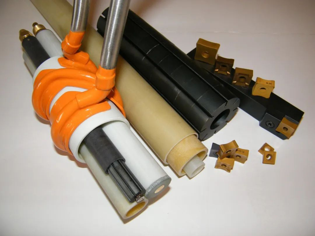
A large number of experiments show that under the premise of placing the magnetic rod (impedance device), the current density is high in the interval from the center line of the squeeze roller to the front end of the induction coil; in the induction coil area, the current density decreases rapidly, and after the induction coil At the end position, the current density drops to 3% of the peak value. After removing the magnetic rod (resistor) in the tube blank, the current density on the edge of the tube blank dropped significantly, and the average drop of the current density in front of the induction coil was about 47%.
Placing a magnet bar in the tube blank can make the induced current in the tube blank gather on the fusion surface, improve the current density on the edge of the tube blank on the fusion surface, thereby improving the induction welding efficiency and saving the power of the high frequency welded pipe equipment. If the magnet bar is not used or the magnet bar fails, it will take more power to maintain production.
It should be noted that if the magnetic rod is packaged inside the resistor, there should be a certain distance between the front end of the resistor and the front end of the magnetic rod. In some literatures, the front of the resistor is placed as the benchmark, and the front end of the resistor is aligned with the center end of the squeeze roller line, so that the front of the magnet bar may be located behind the center line of the squeeze roller, which will reduce the high welding efficiency. The magnet bar in the resistor is an important part that affects the distribution of the induced current. When placing the resistor, the outline of the magnet bar should be used as the benchmark.
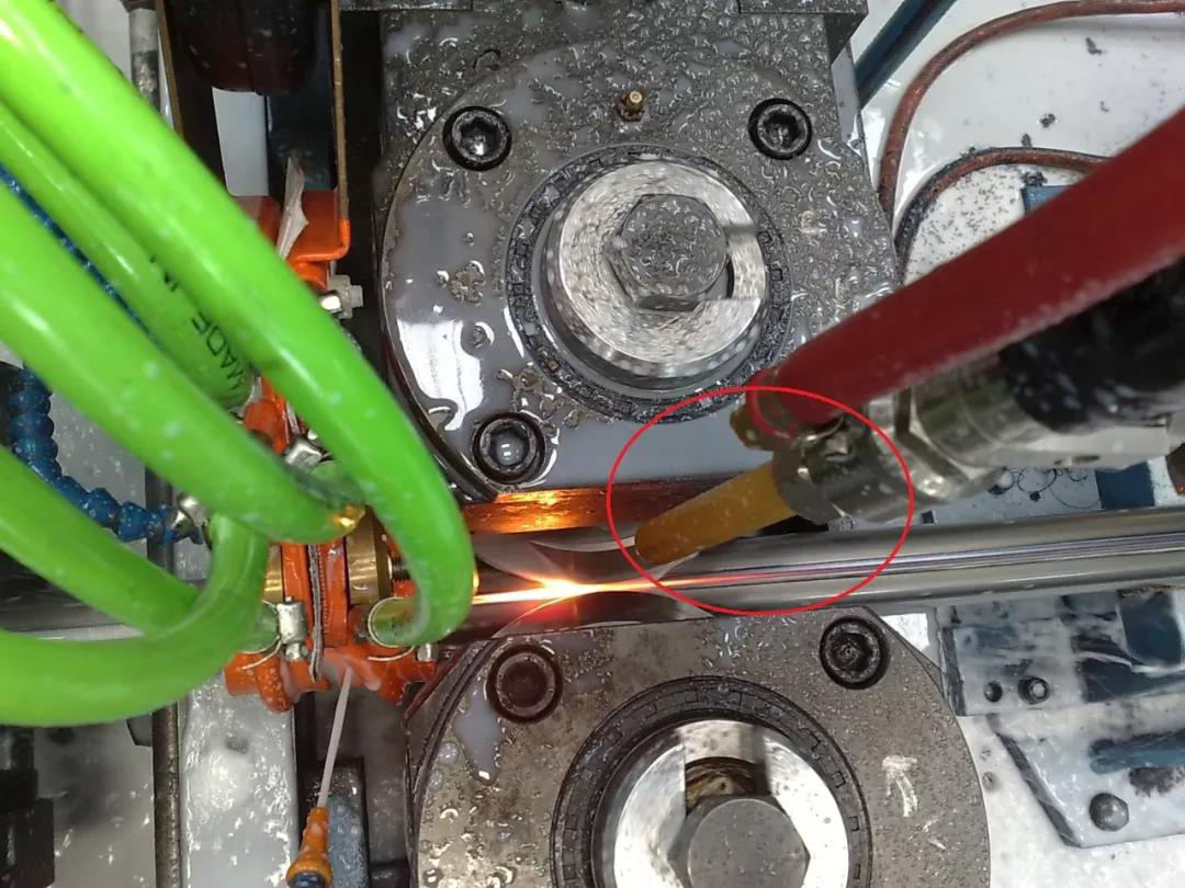
Practical experience suggests that the length of the bar magnet should be 3.5 times the width of the induction coil, but this view is less general. When determining the length of the magnet bar, it should be based on the distribution of the induced current in the axial direction of the welded pipe. In the induction welding process of high frequency welded pipe equipment, the induced current is mainly distributed in the interval from the center line of the squeeze roller to the rear end of the induction coil. Aligning the front end of the magnetic bar with the center line of the extrusion roller, and the rear end of the magnetic bar and the back end of the induction coil coincide, so that most of the induced current in the tube blank can be concentrated on the fusion surface of the welded tube by the action of the magnetic bar. The minimum length of the magnet bar can be determined according to the position of the front and rear ends of the induction coil.
Overview:
When placing the impedance, it should be based on the outline of the magnetic rod inside the impedance. In the axial direction of the welded pipe, it is necessary to align the front end of the magnetic bar with the centerline of the squeeze roller. If the front end of the magnet bar is located behind the centerline of the squeeze roller, the induction welding efficiency will be reduced. The length of the magnet bar should not be less than the distance from the center line of the squeeze roller to the rear end of the induction coil.
In the vertical direction of the cross-section of the welded pipe, the resistance of the resistor close to the fusion surface of the welded pipe can improve the efficiency of induction welding. The cross-sectional area of the magnetic rod inside the impedance device can meet the production requirements when the cross-sectional area of the inner wall of the welded pipe is over 50%.
More News

Time of issue : 2023-10-31

Time of issue : 2023-10-28

Time of issue : 2023-10-25

Time of issue : 2023-10-22
Wechat: 13392281699
Email: zty@usedpipemill.com
Company address:No. A99, East Lecong Avenue, Lecong Town, Foshan City, Guangdong Province
Recommendation
Online Inquiry
LINK
Contact Us
Tel (wechat): 13336487288
Wechat:+86 13336487288
WhatsApp:+86 13336487288
Email: zty@usedpipemill.com
Address: No. A99, Lecong Avenue East, Lecong Town, Foshan City, Guangdong Province


